From inside (document excerpt):
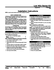
Low NOx Device Kit Cancels: New IIK 330J-60-1 8-95 Installation Instructions NOTE: Read the entire instruction manual before starting the installation. SAFETY CONSIDERATIONS Installing and servicing heating equipment can be hazardous due to gas and electrical components. Only trained personnel should install or service heating equipment. Untrained personnel can perform basic maintenance functions such as cleaning and replacing filters.
All other operations should be performed by trained service personnel. When working on heating equipment, observe precautions in the literature and on tags and labels attached to the unit. Follow all safety codes. Wear safety glass and work gloves. Have a fire extinguisher available. INTRODUCTION This instruction covers the installation of the low NOx device kit Part No. 322562-751 in induced-draft, 2-stage, noncondensing, natural gas furnace models 58DXT, 58UXT, 58UXV, 330JAV, 331JAV, and 333JAV. If more than 1 low NOx device kit is being used, replace 1 device at a time. Do not remove all cell inlet plates at once to avoid shifting of heat exchanger cells. 9. Remove and discard 4 screws from cell inlet plate to be replaced. 10. Remove and discard cell inlet plate or low NOx device being replaced. Step 2–Install New Low NOx Device 1. Install low NOx device using 4 new screws supplied with kit. NOTE: Low NOx bracket (holds coil) should be toward bottom of heat exchanger. When unit is installed in horizontal position, bottom of heat exchanger is nearest the blower. Step 3–Reassemble Furnace 1. Reinstall gas control assembly using 4 saved screws. Do not install in a furnace intended for use with propane gas. This kit contains the following items: Low NOx Device, Cell Inlet Plate Assembly 1 Screws 8 Installation Instructions 1 Step 1–Removal of Existing Low NOx Device or Bracket 1. Turn off gas and electrical supplies to furnace. 2. Remove furnace control doors. 3. Using a backup wrench, disconnect main gas supply from gas valve. 4. Disconnect wiring to hot surface ignitor at plastic connector. 5. Disconnect flame sensor wiring at flame sensor terminal. 6. Note gas valve, limit and control wiring and disconnect as necessary for removal of gas control assembly. 7. Remove and save 4 screws from gas control assembly. 8. Remove gas control assembly. Never use a match or other open flame to check for gas leaks. Use soap-and-water solution. A failure to follow this warning could result in fire, personal injury, or death. 6. Turn on gas supply and check for gas leaks. 7. Replace furnace control door(s). 8. Turn on electrical supply. 9. Check unit for proper operation. 2. Reconnect wires as noted in item 6 above to appropriate connections. (Refer to control wiring diagram on back of blower door if necessary.)


 Carrier Owners Manual - Enlarge page 1 of 2
 2 of 2