From inside (document excerpt):
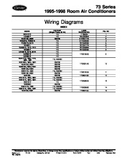
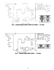
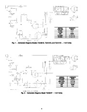
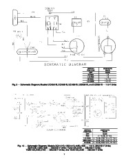
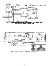
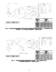
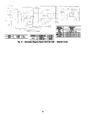
73 Series 1995-1998 Room Air Conditioners Wiring Diagrams INDEX MODEL BCA101D LCA061P HCA313D, 333D TCA051B, TCB051B TCA051D, 061D TCA051L TCA081D, 101D, 121D TCA081P UCA051B, 061B, 081B UCB061B UCD081B XCA121D, 123D, 141D LABEL DIAGRAM NO.
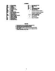
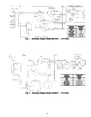
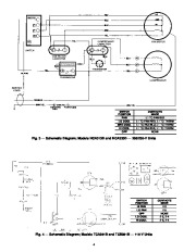
11708034 73LC500334 51HK501744 51TH500404 73TC500284 73TC501774 73TC500554 73TC500454 11708100(A) FIG. NO 11708122(A) 11708001(D) 11 12 11708008(A) 13 11708008(B) 11708001(C) 14 15 Manufacturer reserves the right to discontinue, or change at any time, specifications or designs without notice and without incurring obligations. Book 1 4 PC 131 Catalog No. 537-331 Printed in U.S.A. Form 73-2W Pg 1 5-98 Replaces: New Tab 8a 10a Air Sweep Motor Air Sweep Switdh Capacitor Compressor Fan Cycle Switch Fan Motor Fan Motor Capacitor Hermetic Hermetic Indoor-Fan Motor Indoor-Fan Motor Capacitor Indoor Thermostat Normally Open Outdoor-Fan Motor Outdoor-Fan Motor Capacitor Overload Protector Outdoor Thermostat Primary Limit Switch Power Service Cord Reversing Valve Energy Saver Switch SLS ST SW TM TBH TSI Y — — — — — — — Secondary Limit Switch Start Thermistor Switch Timer Thermostat Bulb Heater Thermal Sensor-Indoor Pilot Light (Yellow) Component Connection (Marked) Component Connection (Unmarked) Accessory or Optional Wiring Common Potential Only Not to Represent Wire) Grounding Bond Plug and Receptable NOTES Recommended for use on grounded power supply only. Compressor and fan motor thermally protected. Dashed lines show start thermistor when used. Cut and insulate blue lead of motor with wire connector (crimp type). (Fig. 7 only.) 5. Red and blue leads of motor will be cut and insulated with wire connector (crimp type).


 Carrier Owners Manual - 1 of 12
 Carrier Owners Manual - 2 of 12
 Carrier Owners Manual - 3 of 12
 Carrier Owners Manual - 4 of 12
 Carrier Owners Manual - 5 of 12
 Carrier Owners Manual - 6 of 12
 Carrier Owners Manual - 7 of 12
 Carrier Owners Manual - 8 of 12
 Carrier Owners Manual - 9 of 12
 Carrier Owners Manual - 10 of 12