From inside (document excerpt):
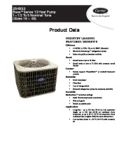
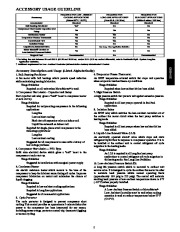
25HBS3 BasetSeries 13 Heat Pump 1 1/2 To 5 Nominal Tons (Sizes 18 60) Product Data INDUSTRY LEADING FEATURES / BENEFITS Efficiency S 13 SEER/ 11 EER / Up to 8.6 HSPF (Nominal) S Microtube Technologyt refrigeration system S Indoor air quality accessories available Sound S Sound level as low as 74 dBA S Sound levels as low as 72 dBA with accessory sound blanket Comfort S System supports Thermidistatt or standard thermostat controls Reliability S Scroll compressor S Filter drier S Loss of charge switch S Balanced refrigeration system for maximum reliability Durability WeatherArmort protection package: S Solid, Durable sheet metal construction S Wire coil guard S Baked–on powder paint Applications S Long–line — up to 250 feet (76.20 m) total equivalent length, up to 200 feet (60.96 m) condenser above evaporator, or up to 60 ft.
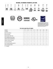
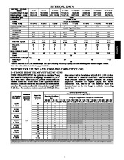
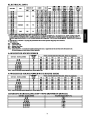
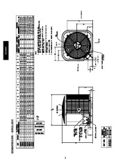
(18.29 m) evaporator above condenser (See Longline Guide for more information.) S Low ambient (down to -20_F/-28.9_C) with accessory kit MODEL NUMBER NOMENCLATURE 1 N 2 2 N 5 3 A H Product Family H = RES HP 4 A B Tier B=Base 5 A/N S Major Series S = R 22 6 N 3 SEER 3=13 SEER 7 N 3 8 N 6 9 A/N A Grille Variations A = Standard G = Dense Coil Guard 10 A/N 0 Open 0=Not Defined 11 A/N 0 Open 0=Not Defined 12 N 3 Voltage 3=208/230 1 5=208/230 3 6=460/3 13 N 0 Series 0= Original Series Product Series 25 = HP Cooling Capacity ISO 9001:2000 REGISTERED 25HBS3 This product has been designed and manufactured to meet Energy Star® criteria for energy efficiency when matched with appropriate coil components. However, proper refrigerant charge and proper air flow are critical to achieve rated capacity and efficiency. Installation of this product should follow all manufacturing refrigerant charging and air flow instructions. Failure to confirm proper charge and air flow may reduce energy efficiency and shorten equipment life. STANDARD FEATURES Feature 13 SEER Scroll Compressor Wire Coil Guard Field Installed Filter Drier Front Seating Service Valves Internal Pressure Relief Valve Internal Thermal Overload Long Line capability Low Ambient capability with Kit Loss of Charge Switch X = Standard 18 X 24 X 30 X 31 X 36 X 42 X 48 X 60 X 2 PHYSICAL DATA UNIT SIZE VOLTAGE, SERIES Operating Weight lb (kg) Shipping Weight lb (kg) Compressor Type REFRIGERANT Control Charge lb (kg) Outdoor Heating Piston # COND FAN Air Discharge Air Qty (CFM) Motor HP Motor RPM COND COIL Face Area Sq ft (m) Fins per In. Rows Circuits VALVE CONNECT. (In. ID) Vapor Liquid REFRIGERANT TUBES (In. OD) Rated Vapor* 5/8 3/4 7/8 1 1/8 Liquid 3/8 *Units are rated with 25 ft (7.6 m) of lineset length. See Vapor Line Sizing and Cooling Capacity Loss table when using other sizes and lengths of lineset. Note: See unit Installation Instruction for proper installation.


 Carrier Owners Manual - 1 of 50
 Carrier Owners Manual - 2 of 50
 Carrier Owners Manual - 3 of 50
 Carrier Owners Manual - 4 of 50
 Carrier Owners Manual - 5 of 50
 Carrier Owners Manual - 6 of 50
 Carrier Owners Manual - 7 of 50
 Carrier Owners Manual - 8 of 50
 Carrier Owners Manual - 9 of 50
 Carrier Owners Manual - 10 of 50