From inside (document excerpt):
Residential Air Conditioners and Heat Pumps Using R 22 and Puronr Refrigerant Application Guideline and Service Manual TABLE OF CONTENTS PAGE UNIT IDENTIFICATION . 2 SAFETY CONSIDERATIONS . 3 INTRODUCTION . 3 INSTALLATION GUIDELINE 3 ACCESSORY DESCRIPTIONS . 4 – 5 LOW-AMBIENT GUIDELINE 6 – 7 LONG LINE GUIDELINE 8 CABINET ASSEMBLY & COMPONENTS . 8 – 10 ELECTRICAL . 11 – 13 Aluminum Wire . 11 Contactor 11 Capacitor 12 Cycle Protector 12 Crankcase Heater 13 Time-Delay Relay .
Heating, Ventilating and Air Conditioning User Manual Free Download. HAVC Operator’s Manual. Auto AC Free Instruction Manual Download PDF.
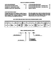
13 PRESSURE SWITCHES . 13 – 14 Low-Pressure Switch (AC only) . 13 High-Pressure Switch (AC & HP) 14 Loss Of Charge Switch (HP only) 14 TECH ASSIST . 14 – 15 DEFROST THERMOSTAT 16 DEFROST CONTROL BOARD . 16 – 19 HK32EA001–Defrost Control 18 HK32EA003–Defrost Control 18 – 19 FAN MOTOR 19 COMPRESSOR PLUG 19 LOW-VOLTAGE TERMINALS . 19 COPELAND SCROLL COMPRESSOR 20 – 23 Compressor Failures 20 Mechanical Failures 20 – 21 Electrical Failures 22 – 23 PAGE REFRIGERATION SYSTEM . 23 – 31 Refrigerant . 23 Compressor Oil 23 Servicing Systems on Roofs With Synthetic Materials 24 Brazing 24 Service Valves and Pump down . 25 – 27 Liquid Line Filter Drier . 28 Suction Line Filter Drier . 28 Accumulator 29 Thermostatic Expansion Valve (TXV) 30 – 31 REFRIGERATION SYSTEM REPAIR 32 – 34 Leak Detection 32 Coil Removal . 32 Compressor Removal and Replacement . 33 System Clean-Up After Burnout 33 Evacuation . 34 CHECK CHARGE 34 TROUBLESHOOTING WITH SUPERHEAT . 34 – 44 TWO-STAGE . 45 – 57 Application Guidelines 45 Airflow Selections for 24ANA7/25HNA6 using Non-Communicating Thermostats . 46 Airflow Selections for FV Fan coils for 24ANA7/25HNA6 using Non-Communicating Thermostats 46 General Information 46 Check Charge . 47 – 48 System Function and Sequence of Operation . 49 Fan Motor 50 – 51 Fan Motor Operation 50 ECM Fan Motor Troubleshooting 51 Time Delays 51 Pressure Switches 51 Muffler, Accumulator, Reversing Valve (RVS) 51 Thermistors . 51 Control Box 52 Troubleshooting . 53 – 57 – TABLE OF CONTENTS (CONTINUED) CARE AND MAINTENANCE 58 – 59 PURON QUICK REFERENCE GUIDE . 59 PRESSURE VS. TEMPERATURE CHART 60 REQUIRED LIQUID LINE TEMPERATURE 61 AC TROUBLESHOOTING CHART 62 HP TROUBLESHOOTING CHART – HEATING CYCLE 63 HP TROUBLESHOOTING CHART – COOLING CYCLE 64 INDEX OF TABLES 65 UNIT IDENTIFICATION Troubleshooting Charts for Air Conditioners and Heat Pumps are provided in the appendix at back of this manual. They enable the service technician to use a systematic approach to locating the cause of a problem and correcting system malfunctions. This section explains how to obtain the model and serial number from unit rating plate. These numbers are needed to service and repair the Puronr and R- air conditioner or heat pump. Model -22 and serial numbers can be found on unit rating plate. AIR CONDITIONER AND HEAT PUMP MODEL NUMBER NOMENCLATURE 1 2 2 4 Series 3 A Family 4 B Tier 5 A Major Series 6 3 SEER 18 24 30 36 42 48 60 7 8 3 6 Cooling Capacity (Tons) = 1– 1/2 =2 = 2– 1/2 =3 = 3– 1/2 =4 =5 9 A Variations 10 0 Open 11 0 Open 12 3 Voltage 13 0 Minor Series 14 0 Packaging 15 0 Parts Identification 0 = Recip. 1 = Scroll 2 = Staged Recip. 3 = Staged Scroll 4 = Other Compr. 1 ….. …


 Carrier Owners Manual - 1 of 66
 Carrier Owners Manual - 2 of 66
 Carrier Owners Manual - 3 of 66
 Carrier Owners Manual - 4 of 66
 Carrier Owners Manual - 5 of 66
 Carrier Owners Manual - 6 of 66
 Carrier Owners Manual - 7 of 66
 Carrier Owners Manual - 8 of 66
 Carrier Owners Manual - 9 of 66
 Carrier Owners Manual - 10 of 66