From inside (document excerpt):
Gasket Kit Cancels: IIK 373L-35-6 IIK 330A-40-1 8-15-93 Part No. 310316-751 & 320887-751 NOTE: Read the entire instruction manual before starting the installation. INTRODUCTION This instruction covers the installation of gasket kit Part No. 310316-751 and 320887-751 on non-condensing, inducedcombustion furnaces. SAFETY CONSIDERATIONS Installing and servicing heating equipment can be hazardous due to gas and electrical components.
Heating, Ventilating and Air Conditioning User Manual Free Download. HAVC Operator’s Manual. Gas Furnace and AC Free Instruction Manual Download PDF.
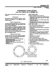
Only trained personnel should install or service heating equipment. Untrained personnel can perform basic maintenance functions such as cleaning coils, or cleaning and replacing filters. All other operations should be performed by trained service personnel. When working on heating equipment, observe precautions in the literature, on tags, and on labels attached to the unit. Follow all safety codes. Wear safety glasses and work gloves. Have a fire extinguisher available. DESCRIPTION AND USAGE The gasket kit is used to restore seals in units where leakage has occurred, or where seals have been damaged during servicing. The gasket kit contains the following items: Gasket for installation between motor mounting bracket and inducer blower housing Gasket for installation between inducer blower housing and collector box Gasket for installation between 11-circuit connector and blower deck Installation Instructions 1 GASKET IDENTIFICATION Each gasket is designed for use in one place only. 1. Largest gasket is for use between motor mounting bracket and inducer blower housing. (Hole pattern will vary slightly depending on kit used.) 2. Second largest gasket is for use between inducer blower housing and collector box. 3. Rectangular gasket is for use between 11-circuit connector and blower deck. (Not used on all hot surface ignition furnaces). GASKET INSTALLATION 1. Turn off gas and electrical supplies to furnace. 2. Remove blower and control access doors. 3. Disassemble furnace components necessary to expose gasket being replaced. 4. Remove old gasket. Ensure old gasket is removed completely and surfaces are clean. 5. Position new gasket in place (a small amount of white glue, such as Elmer’s, may be needed to hold gasket in place). 6. Smooth out all air bubbles and wrinkles so gasket is flat for good seal. 7. Reassemble furnace components. 8. Reinstall blower access door. 9. Turn on gas and electrical supplies to furnace. 10. Start furnace and check for leakage around new gaskets. 11. Operate furnace through 1 complete heating cycle and check for proper operation. 12. Reinstall control access door. 13. Set room thermostat to desired temperature. Installation Instructions A90225 Fig. 1–Gasket Identification Manufacturer reserves the right to discontinue, or change at any time, specifications or designs without notice and without incurring obligations. Book 1 4 PC 101 Catalog.


 Carrier Owners Manual - 1 of 2
 Carrier Owners Manual - 2 of 2