From inside (document excerpt):
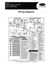
24ACB3 Comfortt Series Air Conditioner 1 1/2 To 5 Nominal Tons Single and Three Phase Wiring Diagrams CONNECTION DIAGRAM BLU BRN CAP YEL H C BLK *CH BLK (NOTE #9) EXTERNAL POWER SUPPLY 24 V (NOTE #3) LEGEND FACTORY POWER WIRING NOTES: 1.
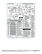
Symbols are electrical representation only. FACTORY CONTROL WIRING *LLS 2. Compressor and fan motor FIELD CONTROL WIRING furnished with inherent thermal protection. FIELD POWER WIRING Y R G 3. To be wired in accordance with INDOOR BLOWER MOTOR INDOOR THERMOSTAT (NOTE #6) COMPONENT CONNECTION National Electric N.E.C. CONDENSING UNIT CHARGING INSTRUCTIONS FIELD SPLICE and local codes. For use with units using R-410A refrigerant 4. N.E.C. class 2, 24V circuit, min. JUNCTION 40 VA required, 60 VA on units PLUG RECEPTACLE REQUIRED LIQUID LINE TEMPERATURE installed with LLS. CONT CONTACTOR 5. Use copper conductors only. Liquid Pressure Required Subcooling Use conductors suitable for at CAP CAPACITOR (DUAL RUN) at Service 1. Only use sub cooling charging method Temperature (ºF) least 75ºC (167ºF). *CH CRANKCASE HEATER Valve (psig) when OD ambient is greater than 70ºF *CHS CRANKCASE HEATER SWITCH 6. Connection for typical cooling 6 8 10 12 14 16 and less than 100ºF, indoor temp is only thermostat. For other COMP COMPRESSOR 251 78 76 74 72 70 68 greater than 70ºF and less than 80ºF, arrangements see installation 259 80 78 76 74 72 70 *CTD COMPRESSOR TIME DELAY and line set is less than 80 ft. instructions.


 Carrier Owners Manual - 1 of 2
 Carrier Owners Manual - 2 of 2